
Dilution refrigerators are among the most powerful systems for reaching ultra-low temperatures in the millikelvin range. They use the phase separation and continuous circulation of ³He–⁴He mixtures to generate cooling, through multiple thermal stages and heat exchangers that progressively reduce the temperature of the circulating helium mixture.
That staged design creates a need for controllable thermal links: paths that provide high thermal conductance when a stage must be cooled, and thermal isolation when it must be left alone. This note looks at two elements of thermal management in the dilution refrigerator at the SRM University-AP quantum reference facility: the silver sintered heat exchanger in the mixing chamber, and a gas gap heat switch used to precool the dilution unit.
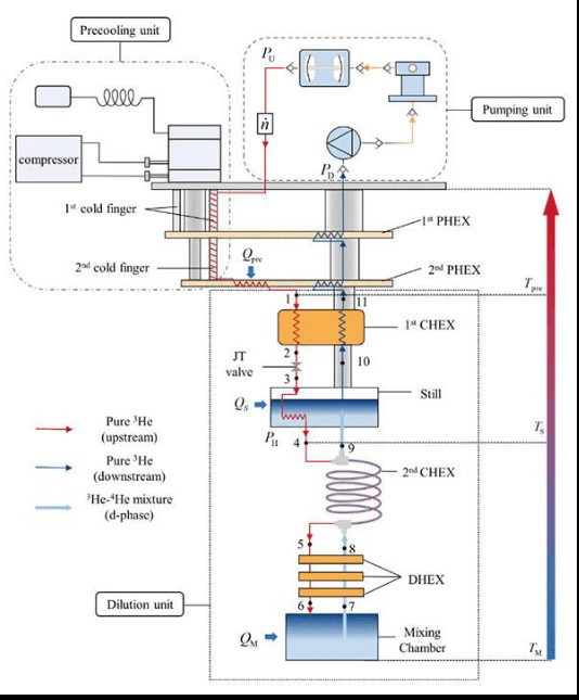
The facility's insert follows the standard stage layout: a 300 K plate, a 50 K plate, a 4 K plate, the still, the cold plate and the mixing chamber.
Silver sintered heat exchanger
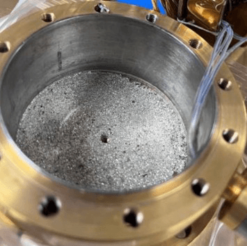
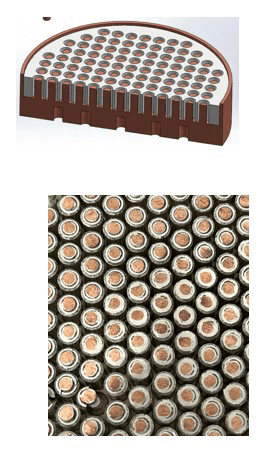
At millikelvin temperatures the thermal boundary resistance between a solid and liquid helium, the Kapitza resistance, becomes a dominant obstacle to heat transfer. A silver sintered heat exchanger addresses this by greatly increasing the contact surface area between the solid and liquid interface.
The effect is strongly temperature-dependent. The product ARKT³ is about 10⁻³ m² K⁴ W⁻¹ at 1 K and rises to about 3 × 10⁻² m² K⁴ W⁻¹ at 0.1 K, which is why the surface area of the sinter matters most at the coldest stage.
Gas gap heat switch
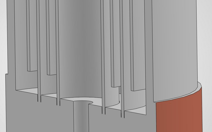
A gas gap heat switch is used to precool the dilution unit. It consists of two conducting copper blocks separated by a small gap. The gap is filled with a highly conducting gas, and changing the gas pressure switches the device between a high-conductance state and a low-conductance state.
The gap pressure is varied with a sorption pump. In the thermal model, a charcoal pump with a heater controls the gas pressure between a hot block and a cold block, which are held apart by a supporting rod.
Three regimes, set by the Knudsen number
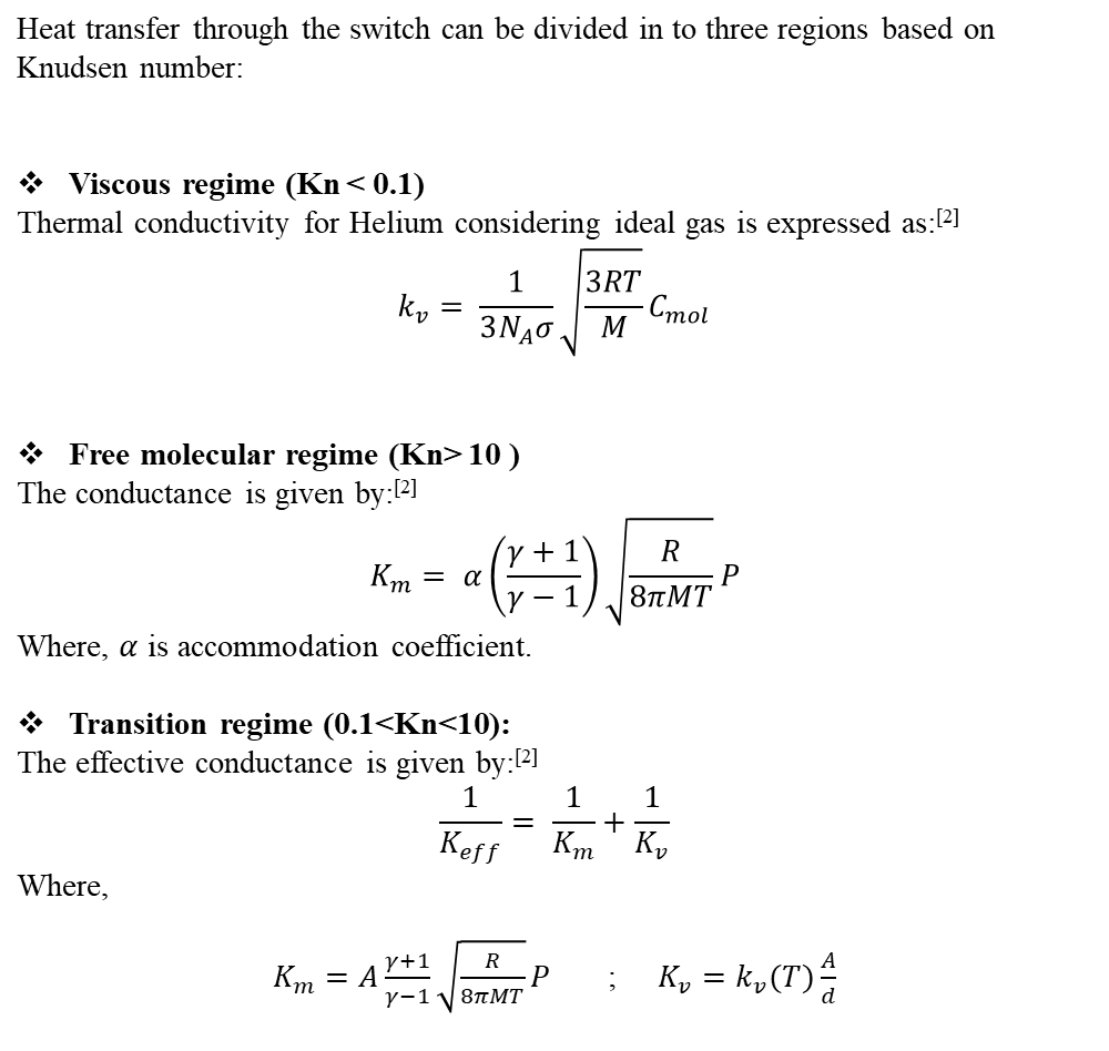
Heat transfer through the switch divides into three regions based on the Knudsen number, Kn. In the viscous regime (Kn < 0.1) the conductance follows the thermal conductivity of the helium gas. In the free molecular regime (Kn > 10) it scales with pressure and depends on the accommodation coefficient. Between them, in the transition regime (0.1 < Kn < 10), the effective conductance combines the two contributions in series.
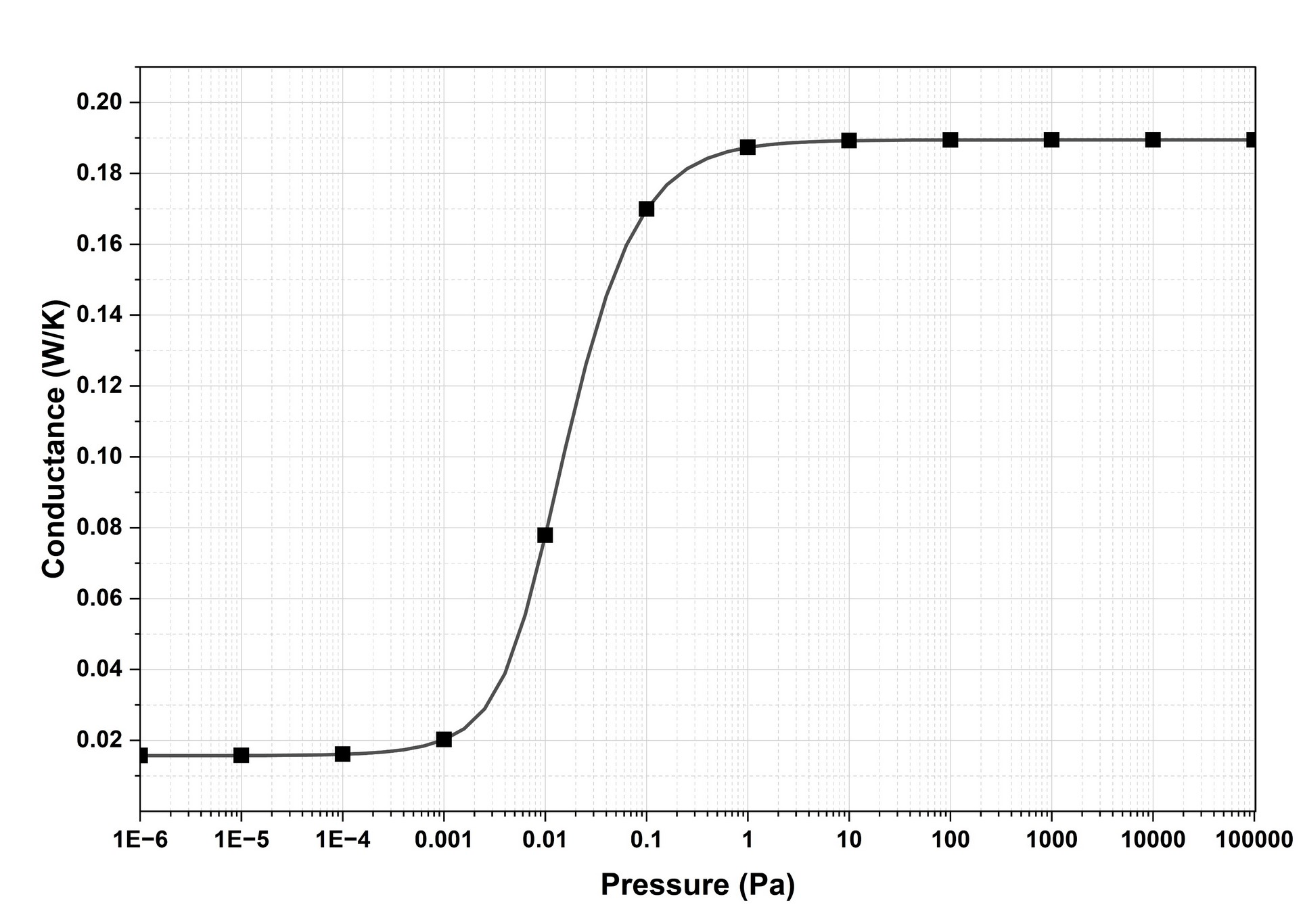
An ON/OFF ratio of about 12
Modelling the switch across charging pressures shows a clear molecular regime (the OFF state), a transition, and a viscous regime (the ON state). The analysis identifies the maximum charging pressure for the OFF state and the minimum charging pressure for the ON state.
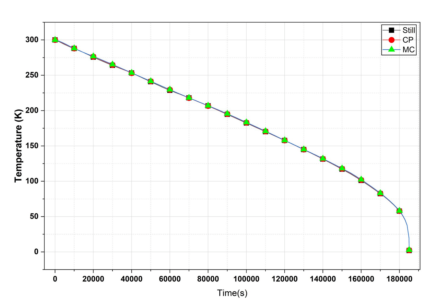
With 2 W of cooling power, the simulation shows the still, cold plate and mixing chamber coming into thermal equilibrium and reaching 4 K in about 51 hours.
Advantages
Further reading
- Zhai, Yujia, and Haizheng Dang. “Performance optimization of a mK dilution refrigerator based on the first law of thermodynamics.” Cryogenics 135 (2023): 103731.
- Wang, Kun, et al. “Design and characterization of an alumina coated helium gas gap heat switch with adjustable gap width.” Cryogenics (2025): 104275.